For testing a steam trap, there should be an isolating valve provided in the downstream of the trap and a test valve shall be provided in the trap discharge. When the test valve is opened, the following points have to be observed :
Condensate discharge-Inverted bucket and thermodynamic disc traps should have intermittent condensate discharge. Float and thermostatic traps should have a continuous condensate discharge. Thermostatic traps can have either continuous or intermittent discharge depending upon the load. If inverted bucket traps are used for extremely small load, it will have a continuous condensate discharge.
Flash steam-This shall not be mistaken for a steam leak through the trap. The users sometimes get confused between a flash steam and leaking steam. The flash steam and the leaking steam can be approximately identified as follows :
Whenever a trap fails to operate and the reasons are not readily apparent, the discharge from the trap should be observed. A step-by-step analysis has to be carried out mainly with reference to lack of discharge from the trap, steam loss, continuous flow, sluggish heating, to find out whether it is a system problem or the mechanical problem in the steam trap.
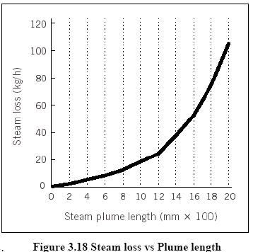
Steam leakage is a visible indicator of waste and must be avoided. It has been estimated that a 3 mm diameter hole on a pipeline carrying 7kg/cm2steam would waste 33 KL of fuel oil per year. Steam leaks on high- pressure mains are prohibitively costlier than on low pressure mains. Any steam leakage must be quickly attended to. In fact, the plant should consider a regular surveillance programme for identifying leaks at pipelines, valves, flanges and joints. Indeed, by plugging all leakages, one may be surprised at the extent of fuel savings, which may reach up to 5% of the steam consumption in a small or medium scale industry or even higher in installations having several process departments.
To avoid leaks it may be worthwhile considering replacement of the flanged joints which are rarely opened in old plants by welded joints. Figure 3.18 provides a quick estimate for steam leakage based on plume length.
Example
The best steam for industrial process heating is the dry saturated steam. Wet steam reduces total heat in the steam. Also water forms a wet film on heat transfer and overloads traps and condensate equipment. Super heated steam is not desirable for process heating because it gives up heat at a rate slower than the condensation heat transfer of saturated steam.
It must be remembered that a boiler without a superheater cannot deliver perfectly dry saturated steam. At best, it can deliver only 95% dry steam. The dryness fraction of steam depends on various factors, such as the level of water to be a part of the steam. Indeed, even as simple a thing as improper boiler water treatment can become a cause for wet steam.
As steam flows through the pipelines, it undergoes progressive condensation due to the loss of heat to the colder surroundings, The extent of the condensation depends on the effectiveness of the lagging. For example, with poor lagging, the steam can become excessively wet.
Since dry saturated steam is required for process equipment, due attention must be paid to the boiler operation and lagging of the pipelines.
Wet steam can reduce plant productivity and product quality, and can cause damage to most items of plant and equipment. Whilst careful drainage and trapping can remove most of the water, it will not deal with the water droplets suspended in the steam. To remove these suspended water droplets, separators are installed in steam pipelines.
The steam produced in a boiler designed to generate saturated steam is inherently wet. Although the dryness fraction will vary according to the type of boiler, most shell type steam boilers will produce steam with a dryness fraction of between 95 and 98%. The water content of the steam produced by the boiler is further increased if priming and carryover occur.
A steam separator may be installed on the steam main as well as on the branch lines to reduce wetness in steam and improve the quality of the steam going to the units. By change of direction of steam, steam seperators causes the entrained water particles to be separated out and delivered to a point where they can be drained away as condensate through a conventional steam trap. A few types of seprators are illustrated in the Figure … below
A study of the steam tables would indicate that the latent heat in steam reduces as the steam pressure increases. It is only the latent heat of steam, which takes part in the heating process when applied to an indirect heating system. Thus, it is important that its value be kept as high as possible. This can only be achieved if we go in for lower steam pressures. As a guide, the steam should always be generated and distributed at the highest possible pressure, but utilized at as low a pressure as possible since it then has higher latent heat.
However, it may also be seen from the steam tables that the lower the steam pressure, the lower will be its temperature. Since temperature is the driving force for the transfer of heat at lower steam pressures, the rate of heat transfer will be slower and the processing time greater. In equipment where fixed losses are high (e.g. big drying cylinders), there may even be an increase in steam consumption at lower pressures due to increased processing time. There are, however, several equipment in certain industries where one can profitably go in for lower pressures and realize economy in steam consumption without materially affecting production time.
Therefore, there is a limit to the reduction of steam pressure. Depending on the equipment design, the lowest possible steam pressure with which the equipment can work should be selected without sacrificing either on production time or on steam consumption.
The heating of a liquid by direct injection of steam is often desirable. The equipment required is relatively simple, cheap and easy to maintain. No condensate recovery system is necessary. The heating is quick, and the sensible heat of the steam is also used up along with the latent heat, making the process thermally efficient. In processes where dilution is not a problem, heating is done by blowing steam into the liquid (i.e) direct steam injection is applied. If the dilution of the tank contents and agitation are not acceptable in the process (i.e)direct steam agitation are not acceptable, indirect steam heating is the only answer.
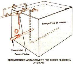
Ideally, the injected steam should be condensed completely as the bubbles rise through the liquid. This is possible only if the inlet steam pressures are kept very low—around 0.5kg/cm2 –and certainly not exceeding 1 kg/cm2. If pressures are high, the velocity of the steam bubbles will also be high and they will not get sufficient time to condense before they reach the surface. Figure 3.20 shows a recommended arrangement for direct injection of steam. A large number of small diameter holes (2 to 5mm), facing downwards, should be drilled on the separate pipe. This will help in dissipating the velocity of bubbles in the liquid. A thermostatic control of steam admitted is highly desirable
The metal wall may not be the only barrier in a heat transfer process. There is likely to be a film of air, condensate and scale on the steam side. On the product side there may also be baked-on product or scale, and a stagnant film of product.
Agitation of the product may eliminate the effect of the stagnant film, whilst regular cleaning on the product side should reduce the scale.
Regular cleaning of the surface on the steam side may also increase the rate of heat transfer by reducing the thickness of any layer of scale, however, this may not always be possible. This layer may also be reduced by careful attention to the correct operation of the boiler, and the removal of water droplets carrying impurities from the boiler.
(Figure 3.21 Water Hammer)
Filmwise condensation
The elimination of the condensate film, is not quite as simple. As the steam condenses to give up its enthalpy of evaporation, droplets of water may form on the heat transfer surface. These may then merge together to form a continuous film of condensate. The condensate film may be between 100 and 150 times more resistant to heat transfer than a steel heating surface, and 500 to 600 times more resistant than copper.
Dropwise condensation
If the droplets of water on the heat transfer surface do not merge immediately and nocontinuous condensate film is formed, ‘dropwise’ condensation occurs. The heat transfer rates which can be achieved during dropwise condensation, are generally much higher than those achieved during filmwise condensation.
As a larger proportion of the heat transfer surface is exposed during dropwise condensation, heat transfer coefficients may be up to ten times greater than those for filmwise condensation. In the design of heat exchangers where dropwise condensation is promoted, the thermal resistance it produces is often negligible in comparison to other heat transfer barriers. However, maintaining the appropriate conditions for dropwise condensation have proved to be very difficult to achieve.
If the surface is coated with a substance that inhibits wetting, it may be possible to maintain dropwise condensation for a period of time. For this purpose, a range of surface coatings such as Silicones, PTFE and an assortment of waxes and fatty acids are sometimes applied to surfaces in a heat exchanger on which condensation is to be promoted. However, these coatings will gradually lose their effectiveness due to processes such as oxidation or fouling, and film condensation will eventually predominate.
As air is such a good insulator, it provides even more resistance to heat transfer. Air may be between 1 500 and 3 000 times more resistant to heat flow than steel, and 8 000 to 16 000 more resistant than copper. This means that a film of air only 0.025 mm thick may resist as much heat transfer as a wall of copper 400 mm thick! Of course all of these comparative relationships depend on the temperature profiles across each layer.
Figure 3.21 illustrates the effect this combination of layers has on the heat transfer process. These barriers to heat transfer not only increase the thickness of the entire conductive layer, but also greatly reduce the mean thermal conductivity of the layer.
The more resistant the layer to heat flow, the larger the temperature gradient is likely to be. This means that to achieve the same desired product temperature, the steam pressure may need to be significantly higher.
The presence of air and water films on the heat transfer surfaces of either process or space heating applications is not unusual. It occurs in all steam heated process units to some degree.
To achieve the desired product output and minimise the cost of process steam operations, a high heating performance may be maintained by reducing the thickness of the films on the condensing surface. In practice, air will usually have the most significant effect on heat transfer efficiency, and its removal from the supply steam will increase heating performance.
When steam is first admitted to a pipe after a period of shutdown, the pipe is full of air. Further amounts of air and other non-condensable gases will enter with the steam, although the proportions of these gases are normally very small compared with the steam. When the steam condenses, these gases will accumulate in pipes and heat exchangers. Precautions should be taken to discharge them. The consequence of not removing air is a lengthy warming up period, and a reduction in plant efficiency and process performance.
Air in a steam system will also affect the system temperature. Air will exert its own pressure within the system, and will be added to the pressure of the steam to give a total pressure. Therefore, the actual steam pressure and temperature of the steam/air mixture will be lower than that suggested by a pressure gauge.
Of more importance is the effect air has upon heat transfer. A layer of air only 1 mm thick can offer the same resistance to heat as a layer of water 25 µm thick, a layer of iron 2 mm thick or a layer of copper 15 mm thick. It is very important therefore to remove air from any steam system.
Automatic air vents for steam systems (which operate on the same principle as thermostatic steam traps) should be fitted above the condensate level so that only air or steam/air mixtures can reach them. The best location for them is at the end of the steam mains.
The discharge from an air vent must be piped to a safe place. In practice, a condensate line falling towards a vented receiver can accept the discharge from an air vent.
In addition to air venting at the end of a main, air vents should also be fitted:
The steam condenses after giving off its latent heat in the heating coil or the jacket of the process equipment. A sizable portion (about 25%) of the total heat in the steam leaves the process equipment as hot water. Figure 3.23 compares the amount of energy in a kilogram of steam and condensate at the same pressure. The percentage of energy in condensate to that in steam can vary from 18% at 1 bar g to 30% at 14 bar g; clearly the liquid condensate is worth reclaiming.
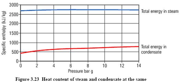
If this water is returned to the boiler house, it will reduce the fuel requirements of the boiler. For every 60C rise in the feed water temperature, there will be approximately 1% saving of fuel in the boiler.
Benefits of condensate recovery
Financial reasons
Condensate is a valuable resource and even the recovery of small quantities is often economically justifiable. The discharge from a single steam trap is often worth recovering.
Un-recovered condensate must be replaced in the boiler house by cold make-up water with additional costs of water treatment and fuel to heat the water from a lower temperature.
Water charges
Any condensate not returned needs to be replaced by make-up water, incurring further water charges from the local water supplier.
Effluent restrictions
High temperature of effluent is detrimental to the environment and may damage to pipes. Condensate above this temperature must be cooled before it is discharged, which may incur extra energy costs.
Maximising boiler output
Colder boiler feedwater will reduce the steaming rate of the boiler. The lower the feedwater temperature, the more heat, and thus fuel needed to heat the water.
Boiler feedwater quality
Condensate is distilled water, which contains almost no total dissolved solids (TDS). Boilers need to be blown down to reduce their concentration of dissolved solids in the boiler water. Returning more condensate to the feedtank reduces the need for blowdown and thus reduces the energy lost from the boiler.
Summary of reasons for condensate recovery:
Heat can be lost due to radiation from steam pipes. As an example while lagging steam pipes, it is common to see leaving flanges uncovered. An uncovered flange is equivalent to leaving 0.6 metre of pipe line unlagged. If a 0.15 m steam pipe diameter has 5 uncovered flanges, there would be a loss of heat equivalent to wasting 5 tons of coal or 3000 litres of oil a year. This is usually done to facilitate checking the condition of flange but at the cost of considerable heat loss. The remedy is to provide easily detachable insulation covers, which can be easily removed when necessary. The various insulating materials used are cork, Glass wool, Rock wool and Asbestos.
The following table 3.3 indicates the heat loss from a hot uninsulated surface to the environment:
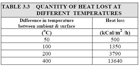
This is based on 35oC ambient temperature, 0.9 emissivity factor and still wind conditions. The effective insulation of a steam system can bring down the heat losses to less than 75 kCal/m2/h.
Note : Calculation procedure to find out the economic thickness of insulation is given in chapter-5: Insulation and Refractories.
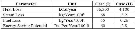
Case Study to elaborate the effect of insulation of flanges: 100 ft of 6 Inch pipe 12 Flanges of 6 Inch = 5 ft of pipe length Heat loss in following 2 cases:
Case (I) – Bare pipe
Case (II) – Pipe with 2 inch insulation aluminum cladding
Flash steam is produced when condensate at a high pressure is released to a lower pressure and can be used for low pressure heating.
The higher the steam pressure and lower the flash steam pressure the greater the quantity of flash steam that can be generated. In many cases, flash steam from high pressure equipments is made use of directly on the low pressure equipments to reduce use of steam through pressure reducing valves.
The flash steam quantity can be calculated by the following formula with the help of a steam table:
![]()
Where:
S1 is the sensible heat of higher pressure condensate.
S2is the sensible heat of the steam at lower pressure (at which it has been flashed).
L2is the latent heat of flash steam (at lower pressure).
The equipments should be supplied with steam as dry as possible. The plant should be made efficient. For example, if any product is to be dried such as in a laundry, a press could be used to squeeze as much water as possible before being heated up in a dryer using steam. Therefore, to take care of the above factors, automatic draining is essential and can be achieved by steam traps. The trap must drain condensate, to avoid water hammer, thermal shock and reduction in heat transfer area. The trap should also evacuate air and other non- condensable gases, as they reduce the heat transfer efficiency and also corrode the equipment. Thus, a steam trap is an automatic valve that permits passage of condensate, air and other non-condensable gases from steam mains and steam using equipment, while preventing the loss of steam in the distribution system or equipment.
The energy saving is affected by following measures:
When the steam reaches the place where its heat is required, it must be ensured that the steam has no more work to do than is absolutely necessary. Air-heater batteries, for example, which provide hot air for drying, will use the same amount of steam whether the plant is fully or partly loaded. So, if the plant is running only at 50 per cent load, it is wasting twice as much steam (or twice as much fuel) than necessary. Always use the most economical way to removing the bulk of water from the wet material. Steam can then be used to complete the process. For this reason, hydro-extractors, spin dryers, squeeze or calendar rolls, presses, etc. are initially used in many drying processes to remove the mass of water. The efficiency with which this operation is carried out is most important. For example, in a laundry for finishing sheets (100 kg/hr. dry weight), the normal moisture content of the sheets as they leave the hydro extractor, is 48% by weight.
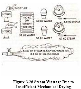
Thus, the steam heated iron has to evaporate nearly 48kg of water. This requires 62kg of steam. If, due to inefficient drying in the hydro-extractor, the steam arrive at the iron with 52% moisture content i.e. 52kg of water has to be evaporated, requiring about 67 kg of steam. So, for the same quantity of finished product, the steam consumption increases by 8 per cent. This is illustrated in Figure 3.26.