The purpose of installing the steam traps is to obtain fast heating of the product and equipment by keeping the steam lines and equipment free of condensate, air and non-condensable gases. A steam trap is a valve device that discharges condensate and air from the line or piece of equipment without discharging the steam.
The three important functions of steam traps are:
There are three basic types of steam trap into which all variations fall, all three are classified by International Standard ISO 6704:1982.
The temperature of saturated steam is determined by its pressure. In the steam space, steam gives up its enthalpy of evaporation (heat), producing condensate at steam temperature. As a result of any further heat loss, the temperature of the condensate will fall. A thermostatic trap will pass condensate when this lower temperature is sensed. As steam reaches the trap, the temperature increases and the trap closes.
This range of steam traps operates by sensing the difference in density between steam and condensate. These steam traps include 'ball float traps' and 'inverted bucket traps'. In the 'ball float trap', the ball rises in the presence of condensate, opening a valve which passes the denser condensate. With the 'inverted bucket trap', the inverted bucket floats when steam reaches the trap and rises to shut the valve. Both are essentially 'mechanical' in their method of operation.
Thermodynamic steam traps rely partly on the formation of flash steam from condensate. This group includes 'thermodynamic', 'disc', 'impulse' and 'labyrinth' steam traps.
Some of the important traps in industrial use are explained as follows:
The inverted bucket steam trap is shown in Figure 3.5. As its name implies, the mechanism consists of an inverted bucket which is attached by a lever to a valve. An essential part of the trap is the small air vent hole in the top of the bucket. Figure 3.5 shows the method of operation. In (i) the bucket hangs down, pulling the valve off its seat. Condensate flows under the bottom of the bucket filling the body and flowing away through the outlet. In (ii) the arrival of steam causes the bucket to become buoyant, it then rises and shuts the outlet. In (iii) the trap remains shut until the steam in the bucket has condensed or bubbled through the vent hole to the top of the trap body. It will then sink, pulling the main valve off its seat. Accumulated condensate is released and the cycle is repeated.
In (ii), air reaching the trap at start-up will also give the bucket buoyancy and close the valve. The bucket vent hole is essential to allow air to escape into the top of the trap for eventual discharge through the main valve seat. The hole, and the pressure differential, are small so the trap is relatively slow at venting air. At the same time it must pass (and therefore waste) a certain amount of steam for the trap to operate once the air has cleared. A parallel air vent fitted outside the trap will reduce start-up times.
Advantages of the inverted bucket steam trap
Disadvantages of the inverted bucket steam trap
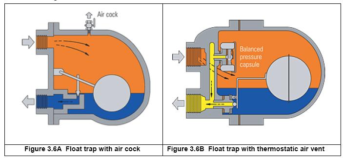
The ball float type trap operates by sensing the difference in density between steam and condensate. In the case of the trap shown in Figure 3.6A, condensate reaching the trap will cause the ball float to rise, lifting the valve off its seat and releasing condensate. As can be seen, the valve is always flooded and neither steam nor air will pass through it, so early traps of this kind were vented using a manually operated cock at the top of the body. Modern traps use a thermostatic air vent, as shown in Figure 3.6B. This allows the initial air to pass whilst the trap is also handling condensate.
The automatic air vent uses the same balanced pressure capsule element as a thermostatic steam trap, and is located in the steam space above the condensate level. After releasing the initial air, it remains closed until air or other non-condensable gases accumulate during normal running and cause it to open by reducing the temperature of the air/steam mixture. The thermostatic air vent offers the added benefit of significantly increasing condensate capacity on cold start-up.
In the past, the thermostatic air vent was a point of weakness if waterhammer was present in the system. Even the ball could be damaged if the waterhammer was severe. However, in modern float traps the air vent is a compact, very robust, all stainless steel capsule, and the modern welding techniques used on the ball makes the complete float-thermostatic steam trap very robust and reliable in waterhammer situations.
In many ways the float-thermostatic trap is the closest to an ideal steam trap. It will discharge condensate as soon as it is formed, regardless of changes in steam pressure.
Advantages of the float-thermostatic steam trap
Disadvantages of the float-thermostatic steam trap
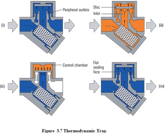
The thermodynamic trap is an extremely robust steam trap with a simple mode of operation. The trap operates by means of the dynamic effect of flash steam as it passes through the trap, as depicted in Figure 3.7. The only moving part is the disc above the flat face inside the control chamber or cap.
On start-up, incoming pressure raises the disc, and cool condensate plus air is immediately discharged from the inner ring, under the disc, and out through three peripheral outlets (only 2 shown, Figure 3.7, i).
Hot condensate flowing through the inlet passage into the chamber under the disc drops in pressure and releases flash steam moving at high velocity. This high velocity creates a low pressure area under the disc, drawing it towards its seat (Figure 3.7, ii).
At the same time, the flash steam pressure builds up inside the chamber above the disc, forcing it down against the incoming condensate until it seats on the inner and outer rings. At this point, the flash steam is trapped in the upper chamber, and the pressure above the disc equals the pressure being applied to the underside of the disc from the inner ring. However, the top of the disc is subject to a greater force than the underside, as it has a greater surface area.
Eventually the trapped pressure in the upper chamber falls as the flash steam condenses. The disc is raised by the now higher condensate pressure and the cycle repeats (Figure 3.7, iv).
Thermal-element thermostatic traps are temperature actuated. On startup the thermal element is in a contracted position with the valve wide-open, purging condensate, air, and other noncondensable gases. As the system warms up, heat generates pressure in the thermal element, causing it to expand and throttle the flow of hot condensate through the discharge valve.
When steam follows the hot condensate into the trap, the thermal element fully expands, closing the trap. If condensate enters the trap during system operation, it cools the element, contracting it off the seat, and quickly discharging condensate (Figure 3.8).
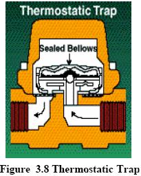
Thermostatic traps are small, lightweight, and compact. One trap operates over extremely broad pressure and capacity ranges. Thermal elements can be selected to operate within a range of steam temperatures. In steam tracing applications it may be desirable to actually back up hot condensate in the lines to extract its thermal value.
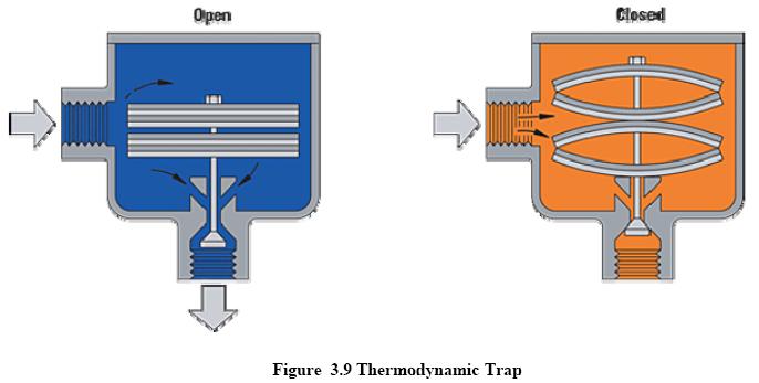
Bimetallic steam traps operate on the same principle as a heating thermostat. A bimetallic strip or wafer connected to a valve bends or distorts when subjected to a change in temperature. When properly calibrated, the valve closes off against a seat when steam is present, and opens when condensate, air, and other non condensable gases are present (Figure 3.9).
Advantages of the bimetallic steam trap
Disadvantages
In most cases, trapping problems are caused by bad installation rather than by the choice of the wrong type or faulty manufacture. To ensure a trouble-free installation, careful consideration should be given to the drain point, pipe sizing, air venting, steam locking, group trapping vs. individual trapping, dirt, water hammer, lifting of the condensate, etc.
1) Drain Point
The drain point should be so arranged that the condensate can easily flow into the trap. This is not always appreciated. For example, it is useless to provide a 15mm drain hole in the bottom of a 150 mm steam main, because most of the condensate will be carried away by the steam velocity. A proper pocket at the lowest part of the pipe line into which the condensate can drop of at least 100mm diameter is needed in such cases.
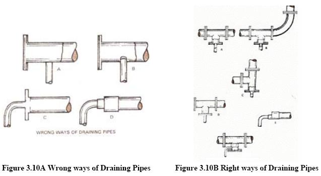
Figures 3.10A and 3.10B show the wrong and the correct practices in providing the drain points on the steam lines.
2) Pipe Sizing
The pipes leading to and from steam traps should be of adequate size. This is particularly important in the case of thermodynamic traps, because their correct operation can be disturbed by excessive resistance to flow in the condensate pipe work. Pipe fittings such as valves, bends and tees close to the trap will also set up excessive backpressures in certain circumstances.
3) Air Binding
When air is pumped into the trap space by the steam, the trap function ceases. Unless adequate provision is made for removing air either by way of the steam trap or a separate air vent, the plant may take a long time in warming up and may never give its full output.
4) Steam Locking
This is similar to air binding except that the trap is locked shut by steam instead of air. The typical example is a drying cylinder. It is always advisable to use a float trap provided with a steam lock release arrangement.
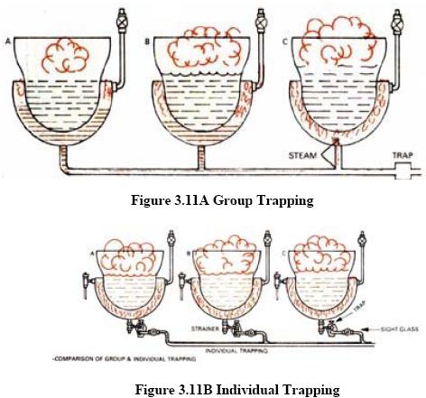
5) Group Trapping vs. Individual Trapping
It is tempting to try and save money by connecting several units to a common steam trap as shown in Figure 3.11A. This is known as group trapping. However, it is rarely successful, since it normally causes water-logging and loss of output.
The steam consumption of a number of units is never the same at a moment of time and therefore, the pressure in the various steam spaces will also be different. It follows that the pressure at the drain outlet of a heavily loaded unit will be less than in the case of one that is lightly or properly loaded. Now, if all these units are connected to a common steam trap, the condensate from the heavily loaded and therefore lower pressure steam space finds it difficult to reach the trap as against the higher pressure condensate produced by lightly or partly loaded unit. The only satisfactory arrangement, thus would be to drain each steam space with own trap and then connect the outlets of the various traps to the common condensate return main as shown in above Figure 3.11B.
6) Dirt
Dirt is the common enemy of steam traps and the causes of many failures. New steam systems contain scale, castings, weld metal, piece of packing and jointing materials, etc. When the system has been in use for a while, the inside of the pipe work and fittings, which is exposed to corrosive condensate can get rusted. Thus, rust in the form of a fine brown powder is also likely to be present. All this dirt will be carried through the system by the steam and condensate until it reaches the steam trap. Some of it may pass through the trap into the condensate system without doing any harm, but some dirt will eventually jam the trap mechanism. It is advisable to use a strainer positioned before the steam trap to prevent dirt from passing into the system.
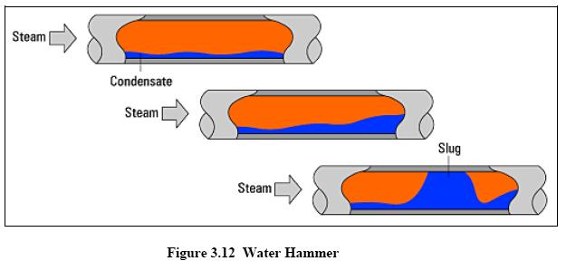
7)Water Hammer
A water hammer (Figure 3.12) in a steam system is caused by condensate collection in the plant or pipe work picked up by the fast moving steam and carried along with it. When this collection hits obstructions such as bends, valves, steam traps or some other pipe fittings, it is likely to cause severe damage to fittings and equipment and result in leaking pipe joints. The problem of water hammer can be eliminated by positioning the pipes so that there is a continuous slope in the direction of flow. A slope of at least 12mm in every 3 metres is necessary, as also an adequate number of drain points every 30 to 50 metres.
8)Lifting the condensate
It is sometimes necessary to lift condensate from a steam trap to a higher level condensate return line (Figure 3.13). The condensate will rise up the lifting pipework when the steam pressure upstream of the trap is higher than the pressure downstream of the trap.
The pressure downstream of the trap is generally called backpressure, and is made up of any pressure existing in the condensate line plus the static lift caused by condensate in the rising pipework. The upstream pressure will vary between start-up conditions, when it is at its lowest, and running conditions, when it is at its highest.
Backpressure is related to lift by using the following approximate conversion: 1 metre lift in pipework = 1 m head static pressure or 0.1 bar backpressure.
If a head of 5 m produces a backpressure of 0.5 bar, then this reduces the differential pressure available to push condensate through the trap; although under running conditions the reduction in trap capacity is likely to be significant only where low upstream pressures are used.
In steam mains at start-up, the steam pressure is likely to be very low, and it is common for water to back-up before the trap, which can lead to waterhammer in the space being drained. To alleviate this problem at start-up, a liquid expansion trap, fitted as shown in Figure 3.13, will discharge any cold condensate formed at this time to waste.
As the steam main is warmed, the condensate temperature rises, causing the liquid expansion trap to close. At the same time, the steam pressure rises, forcing the hot condensate through the ‘working’ drain trap to the return line.
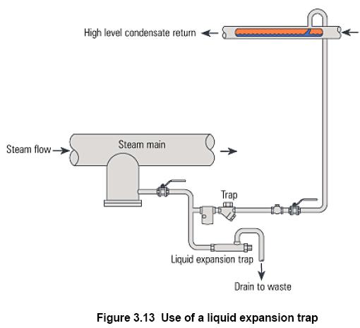
The discharge line from the trap to the overhead return line, preferably discharges into the top of the main rather than simply feed to the underside, as shown in Figure 3.13. This assists operation, because although the riser is probably full of water at start-up, it sometimes contains little more than flash steam once hot condensate under pressure passes through. If the discharge line were fitted to the bottom of the return line, it would fill with condensate after each discharge and increase the tendency for waterhammer and noise.
It is also recommended that a check valve be fitted after any steam trap from where condensate is lifted, preventing condensate from falling back towards the trap. The above general recommendations apply not just to traps lifting condensate from steam mains, but also to traps draining any type of process running at a constant steam pressure. Temperature controlled processes will often run with low steam pressures. Rising condensate discharge lines should be avoided at all costs, unless automatic pump-traps are used.
Dirt is one of the most common causes of steam traps blowing steam. Dirt and scale are normally found in all steam pipes. Bits of jointing material are also quite common. Since steam traps are connected to the lowest parts of the system, sooner or later this foreign matter finds its way to the trap. Once some of the dirt gets logged in the valve seat, it prevents the valve from shutting down tightly thus allowing steam to escape. The valve seal should therefore be quickly cleaned, to remove this obstruction and thus prevent steam loss.
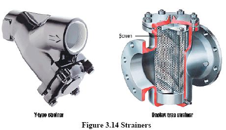
In order to ensure proper working, steam traps should be kept free of pipe-scale and dirt. The best way to prevent the scale and dirt from getting into the trap is to fit a strainer. Strainer (Figure 3.14) is a detachable, perforated or meshed screen enclosed in a metal body. It should be borne in mind that the strainer collects dirt in the course of time and will therefore need periodic cleaning. It is of course, much easier to clean a strainer than to overhaul a steam trap.
At this point, we might mention the usefulness of a sight glass fitted just after a steam trap. Sight glasses are useful in ascertaining the proper functioning of traps and in detecting leaking steam traps. In particular, they are of considerable advantage when a number of steam traps are discharging into a common return line. If it is suspected that one of the traps is blowing steam, it can be quickly identified by looking through the sight glass.
In most industries, maintenance of steam traps is not a routine job and is neglected unless it leads to some definite trouble in the plant. In view of their importance as steam savers and to monitor plant efficiency, the steam traps require considerably more care than is given. One may consider a periodic maintenance schedule to repair and replace defective traps in the shortest possible time, preferable during regular maintenance shut downs in preference to break down repairs.
Actual energy efficiency can be achieved only when
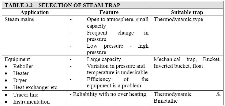
The following Table 3.2 gives installation of suitable traps for different process applications.
Steam trap performance assessment is basically concerned with answering the following two questions:
Traps that fail ‘open’ result in a loss of steam and its energy. Where condensate is not returned, the water is lost as well. The result is significant economic loss, directly via increased boiler plant costs, and potentially indirectly, via decreased steam heating capacity.
Traps that fail ‘closed’ do not result in energy or water losses, but can result in significantly reduced heating capacity and/or damage to steam heating equipment.
Visual testing includes traps with open discharge, sight glasses (Figure 3.15), sight checks, test tees and three way test valves. In every case, the flow or variation of flow is visually observed. This method works well with traps that cycle on/off, or dribble on light load. On high flow or process, due to the volume of water and flash steam, this method becomes less viable. If condensate can be diverted ahead of the trap or a secondary flow can be turned off, the load on the trap will drop to zero or a very minimal amount so the visual test will allow in determining the leakage.
Sound testing includes ultrasonic leak detectors (Figure 3.16), mechanics stethoscopes, screwdriver or metal rod with a human ear against it. All these use the sound created by flow to determine the trap function like the visual method. This method works best with traps that cycle on/off or dribble on light load. Traps which have modulating type discharge patterns are hard to check on high flows. (examples are processes , heat exchangers, air handling coils, etc). Again by diverting condensate flow ahead of the trap or shutting off a secondary flow as mentioned under visual testing, the noise level will drop to zero or a very low level if the trap is operating correctly. If the trap continues to flow heavily after diversion it would be leaking or blowing through.
Temperature testing includes infrared guns (Figure 3.17), surface pyrometers, temperature tapes, and temperature crayons. Typically they are used to gauge the discharge temperature on the outlet side of the trap. In the case of temperature tapes or crayon, they are set for a predetermined temperature and they indicate when temperature exceeds that level. Infrared guns and surface pyrometer can detect temperatures on both sides of the trap. Both the infrared and surface pyrometers require bare pipe and a clean surface to achieve a reasonable reading. The temperature reading will typically be lower than actual internal pipe temperature due to the fact that steel does have some heat flow resistance. Scale on the inside of the pipe can also effect the heat transfer. Some of the more expensive infrared guns can compensate for wall thickness and material differences. Blocked or turned off traps can easily be detected by infrared guns and surface pyrometers, as they will show low or cold temperatures. They could also pick up traps which may be undersized or backing up large amounts of condensate by detecting low temperature readings.
(Figure 3.17 Infra red testing)